chess timer (***In progress)
proof of concept
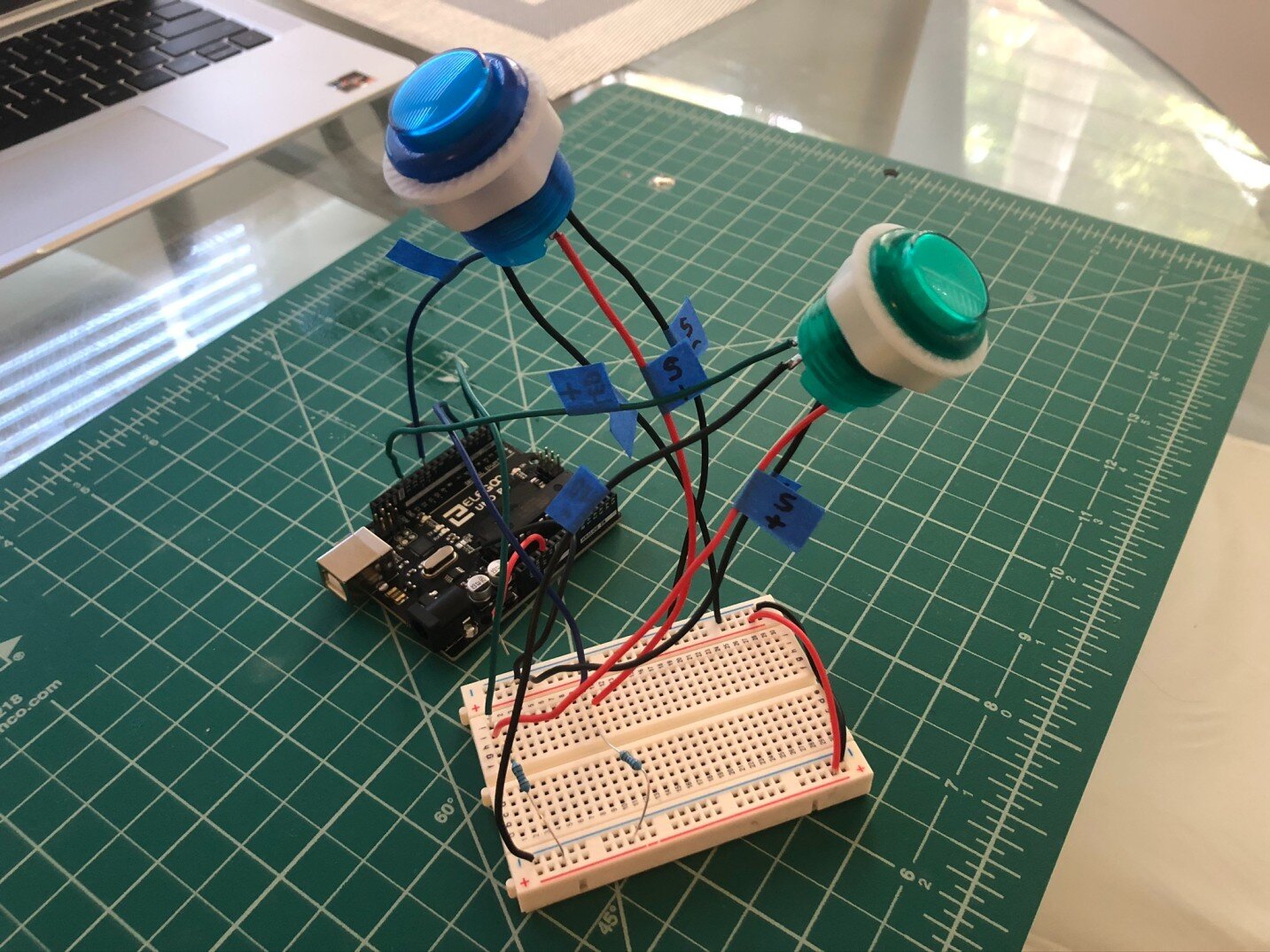
A quick Arduino proof of concept was made to test the buttons under different modes of operation experienced in a typical Chess match (e.g. rapid presses). Each player presses his/her corresponding button to signal the end of a turn. One button illuminates at a time to indicate which player’s turn it is.
Hardware
A full schematic and PCB was then created to implement the following additional features:
ARM microcontroller:
Real-time clock to track each player’s remaining time.
ADC to monitor battery level and detect touchscreen presses.
Analog Watchdog that turns off the device when the battery falls below 3.0V.
SWD programming.
Power and GPIO breakouts for prototyping.
Power Management System (LiPo Battery):
LiPo battery safety (overvoltage, undervoltage, overdischarge, and short circuit protection). Included in purchased LiPo.
LiPo charging through USB (constant current, constant voltage charging).
Appropriate power distribution (USB powered when charging, battery powered otherwise).
Charging status indication (through LED or host microcontroller).
3.3V output from the buck-boost converter when the LiPo battery is between 2.7V - 4.2V.
User Interface:
Touchscreen GUI.
Player Buttons. Input to PWM for brightness control.
SCHEMATIC
PCB
PCB characteristics:
4 layers (Signal - GND - 3.3V - Signal).
74mm x 70mm (2.9in x 2.75in).
Test points to verify charging IC and buck-boost regulator functionality before connecting a LiPo to the circuit (TP1 - TP8).
4x enclosure mounting holes (M3 screws). 3 additional holes to further stabilize PCB to enclosure.
4x display mounting holes.
Manufacturer = JLCPCB.
Full Board Layout
Layer Stackup
Top Layer
GND Layer
3.3V Layer
Bottom Layer
Manufactured PCB (74mm x 70mm)
Display Mounting: Flex cable soldered directly to footprint. Adhesive tape and mounting pegs on display further stabilize it to the PCB


